
 Share
Share
 Print
Print
|
|
|
|
|
Select the Positions ![]() button. The system displays the following screen:
button. The system displays the following screen:
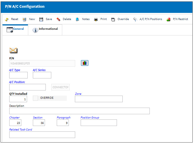
The following information/options are available in this window:
_____________________________________________________________________________________
P/N
The Part Number reference for the aircraft part. This is the part that will have its position defined in this window.
P/N Position Range ![]() button
button
Select this button to apply effectivity to a range of specified S/Ns Line items or to a range of IPCs. For additional information, refer to the Range Button.
A/C Type/Series
The Aircraft Type and Series/Fleet assignment.
A/C Position
The aircraft position reference.
A/C Position/ERD
The Aircraft Position ERD (Equipment Reference Designator) reference. This field is part of the 787Software program used to define the ERD for software parts. This field will only be displayed if the Software Configuration Control checkbox is selected in the A/C Type/Series, General Tab. For additional information, refer to the A/C Type/Series, General Tab, via A/C Type/Series section of the Settings Training Manual.The entries in this field are based on the A/C Positions transaction code. Only Positions with the Equipment Reference Designator checkbox selected will be applicable to the A/C Position/ERD field. For more information refer to A/C Positions via the Settings Transaction Code Training Manual.
From the Drop Down Selection window, users can select the Equipment Reference Designator checkbox to display only ERD Positions.
QTY Installed
The quantity of the installed part.
Override checkbox
Select if an aircraft Tail Number override is required.
Zone
The appropriate zone.
Software Location ![]() button
button
This buttons allows users to select multiple Locations for the P/N Software part to be located. When selected, all available software Locations are displayed. Once the selected are made, click the Select ![]() button to choose the Locations.
button to choose the Locations.
Note: These software Location options are transaction codes that are set up via Settings/Software Location Identifier in the System Transaction Code Explorer.
![]() The Software Location Identifier transaction code is security controlled via Settings/Explorer/System Transaction Code. For more information refer to the Security Explorer via the System Administration Training Manual.
The Software Location Identifier transaction code is security controlled via Settings/Explorer/System Transaction Code. For more information refer to the Security Explorer via the System Administration Training Manual.
Once all selections have been made, red text next to the button indicates the amount of Locations that have been selected. These selected Locations then appear in the Software Configuration Authorization Explorer for the part.
Note: For this functionality to work properly, the parts involved have to be effective to an A/C with the Software Configuration Control checkbox selected. For more information refer to the A/C Type/Series, General Tab via the Settings Training Manual.
Description
A related description.
Chapter / Section / Paragraph
The ATA chapter/section/paragraph, as applicable.
Position Group
The position of the group on the A/C which restricts the installation of two or more both way interchangeable parts in 'matching' groups. If an attempt is made to install parts in 'matching' groups, the system will display an information box informing the user that intermixing is not allowed. The user will not be able to continue with the install transaction.
Related Task Card
The Task Card / Job Card that details the scheduled maintenance work. This is informational only.
_____________________________________________________________________________________
Share
Print
|
©1997-2024 Trax USA Corp. All rights reserved. This manual may not be copied, photocopied, reproduced, translated, or converted to any electronic or machine-readable form, in whole or in part, without prior written approval from Trax USA Corp. |
|